Porcelain Insulator News
by Elton Gish
Reprinted from "Crown Jewels of the Wire", May 1997, page 20
HEWLETT SUSPENSION INSULATORS
I have received several questions on Hewlett suspension insulators over the
last few years from collectors who cannot find any information on these early
and once plentiful insulators. Jack Tod's PIN articles about the Hewlett
insulator were published many years ago. With a lot of new porcelain collectors
in the hobby, it is time that we discuss the Hewlett again. I thought about
writing a simple description with a few photographs and illustrations but that
would still leave a lot of unanswered questions for many of you. Hopefully the
following discussion will answer most of your questions. I certainly learned a
lot about the Hewlett while doing research for the article.
The Hewlett
suspension disks were widely used across the country for several decades and a
few can still be found in service in remote areas. The greatest advantage of
this first practical suspension insulator was the absence of any form of cement.
In contrast, the cap and pin suspension insulator required the use of Portland
cement to secure the metal cap on the top and the metal pin in the hole formed
on the underside. Early attempts at making cap and pin suspension insulators met
with limited success because the weight and strain of the power line often
pulled the metal parts off the insulator and thermal expansion of the cement
frequently caused the porcelain body to crack and fail. Such problems began to
occur just a few years after installation. The Hewlett insulator had none of
these problems. The major disadvantages of the Hewlett disk were complicated
assembly, gross weight of a completed string, and poor electrical properties
which resulted in radio interference. Later improvements in the interconnecting
hardware did make assembly easier. The major advantage of the Hewlett insulator
and its use as a suspension system was allowing the power industry to break the 60,000 volt barrier imposed by the use of multipart
pin-type porcelain insulators. The Hewlett suspension disk allowed construction
of more efficient power lines with voltages of 100,000 volts and higher. In the
late 1910's, the Hewlett was in such great demand that two companies were
granted licenses to produce insulators based on the original General Electric
patent.
In July 1988, I took several photographs of an early installation of
Hewletts at Coal Bank Pass between Durango and Silverton, CO. The photographs
were on slides and I just recently had them converted into prints. Two of the
photographs are shown in this column. Note the very old wooden pole and the
three strings of Hewletts with four insulators in each string. The pole was used
as a corner support for a sharp turn in the 3-phase power line. Note, too, the
metal arcing rings which helped prevent damaging flashovers caused by wet
weather or nearby lightning strikes. A line crew would find access to these
poles difficult because a bucket truck would be out of the question in this very
mountainous region. That probably explains why these Hewlett strings have
survived so long. I would bet that the line has now been upgraded.
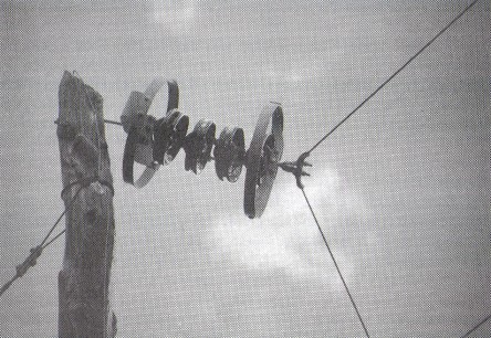
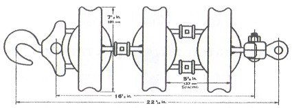
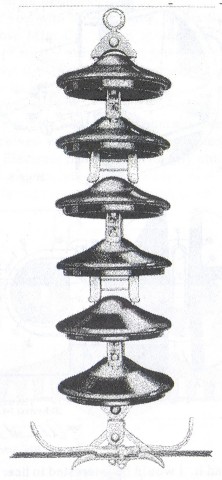
String of four 10" Hewlett suspension insulators with arcing
rings used
to support the strain of the power line turning a
sharp angle. Location is Coal
Bank Pass, CO in 1988.
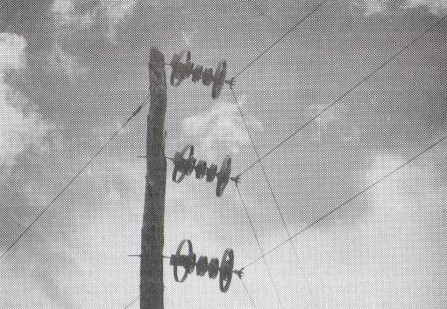
Three strings of Hewlett suspension insulators
at Coal Bank Pass, CO.
The first suspension insulator was patented by Fred Locke on January 10, 1905
(No. 779,659; see my book, Fred M. Locke: A Biography). This design was rigid
with the metal cap and pin either cemented or screwed on the porcelain disk.
Fred Locke did develop other suspension insulator designs which were mostly
impractical because they were either too heavy, difficult to make, or
complicated to assemble. On October 18, 1910, Fred Locke was granted a patent
for a suspension insulator similar to the cap and pin disk which used eye hooks
as connectors. The string of insulators was mounted between two crossarms and
the conductor was attached in the middle of the string. This was not quite the
suspension system that industry later accepted.
On February 25, 1908, John
Duncan was granted a patent for a cap and pin suspension insulator that was
composed of two porcelain shells cemented together. We discussed this insulator
in CJ's PIN a few years ago (11-91-22, 11-93-18, and 5-95-8). This insulator
failed because of cement expansion and specimens today are considered rare.
On
January 25, 1910, A. O. Austin was granted a patent for the first cap and pin
suspension insulator that used a ball and socket
Co. in August 1910. The suspension disk with ball and socket coupling was
shown in the July 1910 Ohio Brass catalog and this basic feature was part of
nearly every suspension insulator offered by O-B for many years.
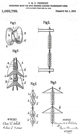
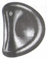
A French
citizen named Charles Priestley took a different approach and obtained a patent
on October 1, 1912, for what we now call the "hog's liver" or
"pork liver" insulator. The insulator was composed of a pair of
saddles disposed of each other with interlocking grooves formed in the porcelain
body to receive metal cables or links (similar to the Hewlett). The interlocking
feature prevented the conductor from dropping to the ground if the porcelain
body was broken. The Priestley patent application was filed on Dec. 20, 1910.
O-B licensed the Priestley patent and cataloged the insulator for many years. It
was not advertised as a suspension insulator but rather as a Link Strain
Insulator. O-B probably considered the link strain inferior to their cap and pin
insulators for suspension service and the interlocking configuration proved
important in strain services.
Ohio Brass acquired the rights to the Priestley patent before the patent was
granted in 1912. The July 1910 and July 1911 O-B catalogs did not show the
Priestley link strain insulator, but the 1912 O-B catalog did show it with the
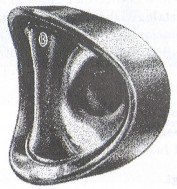
note "Patent Applied For". It offered the following description:
"This insulator is used for horizontal spans or dead-ending feeder wires.
The wire can be easily threaded as the holes are practically straight. The
flanges not only increase the arcing distance, but also provide additional
protection in case of storms. In case the insulator should be broken, the wire
cannot fall as the loop of one piece passes through the other." The working
voltage of the link strain was listed as 11,000 volts.
 |
 |
| Link Strain insulator shown in Ohio Brass catalogs from 1912 (left) and 1919
(right). Note the sharp flange edges on the earlier version and the more rounded
edges on the later version. |
O-B continued to catalog the link strain insulator as late as 1940
(apparently discontinued in 1947 catalog). Note that the illustration of the
link insulator in the 1912 catalog has sharp flange edges and the one in the
1919 catalog shows rounded edges. The change to the rounded edge design occurred
quickly as it was first shown in the 1914 O-B catalog (I don't have a copy of
the 1913 catalog) and continued without change until the link strain was
discontinued.
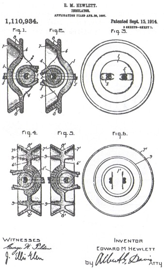
Edward Hewlett developed an insulator that utilized the same
interlocking principle embodied in the Priestley patent. Hewlett was granted
patent No. 1,110,934 on September 15, 1914. The patent application was filed
three years earlier than the Priestley patent on April 30, 1907. The patent was
assigned to the General Electric Co. in Schenectady, NY. The Hewlett was
designed to be washed by rain to reduce contamination effects, maintain a dry
surface area to reduce electrical leakage, and be strong enough to withstand
great strains from the conductor. The new insulator was announced by Hewlett in a paper he
presented at the AlEE annual conference in Niagara Falls on June 26, 1907, and
the paper was later reprinted in the July 20, 1907 issue of Electrical
Review.
Harold Buck and Hewlett worked together at GE on various schemes to put the
new insulator into practical use. Both men jointly applied for a patent on
October 31, 1907, for the construction of a power line using the new insulator.
The system called for four or five vertical suspension strings and the use of
intervening horizontal deadending strings on opposite sides of a crossarm (with
connecting jumper lines). The periodic use of dead-ending strings would reduce the
effects of strains on the power line due to wind and other factors. The
Buck/Hewlett patent was granted on June 22, 1909. Mr. Buck also had an article
published in the July 20, 1907, issue of Electrical Review which gave the
details of power line construction using the Hewlett insulator. The first
significant use of the Hewlett insulator was for the new 100,000 volt line of
the Grand Rapids-Muskegon Power Co. strung on 35 miles of steel towers (reported
in November 2, 1907, issue of Electrical World) parallel to the old 60,000 volt
line which used pin-type insulators on wooden poles.

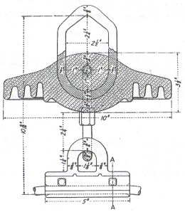
The standard Hewlett shown in the 1920 Thomas catalog
(not hook option).
The Hewlett was the first practical suspension insulator and was very much
like the modern guy strain insulator in that the two connecting cables or links looped inside the porcelain body in such a way as
to make them interlocking. If the insulator broke, the power line would not fall
to the ground. The Hewlett patent actually described two different styles of
link-type
insulators for two different uses -- one for suspension service and the other for
strain service. The suspension insulator is shown in the patent drawings as
Figures 1 and 2 (for vertical installation) and the strain insulator as Figures
4 and 5 (for horizontal installation). The suspension style is what we commonly
refer to as the standard Hewlett insulator. The strain style is called the
"fish-tail" Hewlett because the shape of the outer edge of the disk is
V-shaped like a fish tail. Both styles utilized porcelain at its strongest
potential -- under compression (from the interlocking link connectors), and,
since no cement was used, the Hewlett was free of the problems of cement
expansion and insecure metal parts which plagued the cap and pin suspension
disks.
Thomas "fish-tail" Hewlett dead-ending string
shown in their 1928
catalog.
The original manufacturer of the Hewlett was General Electric. The insulators
were initially supplied without hardware. The disks were connected into strings
by threading cables in the channels formed in the porcelain and the ends were
clamped together with Crosby clips. Needless to say the insulator was difficult
to manufacture and the interconnecting hardware was difficult to assemble. The
Hewlett was expensive to make, proved to be fragile mechanically, and was
vulnerable to lightning flashover, which would not only burn the hardware but
could seriously damage the porcelain. Cap and pin suspension disks were easier
to make and assemble and became very popular between about 1910-1915 until
massive failures were encountered due to the caps and pins pulling out and
breakage of the porcelain disk from cement expansion. The Hewlett quickly
regained popularity until the advent of radio interference caused the design to
be abandoned when the problems with cap and pin insulators were eventually
resolved. Usage of the Hewlett declined throughout the 1930's becoming obsolete by 1940. I have observed many Hewletts still in
service in the 1980' s and early 1990' s but suspect that many of these
installations either have been or will be replaced soon.
GE produce the first
Hewletts at their Schenectady, NY plant and continued producing them for a
number of years. The Hewlett became so popular that GE decided to license the
patent to the R. Thomas & Sons Co. in 1917 and to Locke in 1919. One story
relates how Locke gave GE stock in their company in exchange for license rights
to make the Hewlett. GE gradually withdrew from manufacturing Hewletts and
probably stopped making them by 1925 having transferred all of their interest in
Hewletts to Locke's Baltimore plant. GE became sole owner of Locke in 1935.
It
wasn't long until the complicated interconnecting hardware was improved. In 1917
Thomas designed new hardware composed of two copper V-bolts connected with
galvanized steel couplers which had a flat spring brass clip inserted in the
coupler to make the final secure connection. This unique coupling design
became the standard and propelled Thomas' line of Hewletts into the forefront.
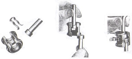
Illustrations of the standard coupler and spring clip
shown in 1928 Thomas
catalog.
The Thomas suspension Hewlett was offered in only the 10-inch diameter size
and advertised as suitable for both suspension and strain service. A typical
installation had either 4, 6, or 8 disks connected into a string but the catalog
indicated that up to 15-disk strings were available. The Thomas
"fish-tail" Hewlett was offered in only two sizes, 6-inch and 7-l/2-inch, with installations composed of
1, 2, 3, or 4 disks in a string. The
6-inch "fish-tail" Hewlett was referred to as the "Baby"
Hewlett.
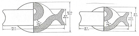
Fish-tail Hewletts: 7-l/2-inch (left) and 6-inch Baby Hewlett (right)
Locke's suspension Hewlett was 10-1/2 inches in diameter (slightly larger
than Thomas' 10-inch Hewlett). The fish-tail Locke Hewlett came in the standard
6-inch and 7-1/2-inch sizes. Locke used the same interconnecting coupling device
and later offered a slightly different version of their own design. Locke
Hewletts have been reported with the LOCKE R=oo insulator logo marking.
Thomas
Hewletts are often unmarked. Marked ones have the following marking:
THOMAS PAT JUNE 22 09 SEPT. 15 14 GECO USA
Various other letters and numbers may be included which might refer to lot
numbers or manufacturing dates. I have a Baby Hewlett with the marking, THOMAS
HEWLETT-35, and a 7-1/2-inch fishtail Hewlett with the marking, PAT SEPT. 15,
14. Some of the unmarked Hewletts were either not struck with the marking
device, slightly struck, or the glaze was so thick it obliterated the marking.
Locke worked to improve the Hewlett design. The channel for the V-bolt link had
to be drilled out after the clay form was dried. Locke tried casting the Hewlett
forming the interlocking channels as part of the casting process, but this
proved unsuccessful. One of the Locke employees came up with a rather simple
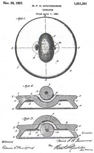
solution. Minor Gouverneur (resident of Victor, NY) was granted a patent on
November 29, 1927 (application filed on April 7, 1921) for a way to cut the
channel while the clay was still plastic (wet). He used a design similar to the
standard Hewlett except the channel projecting above the top surface (and
bottom, too) was tubular (as opposed to dome shaped on the Thomas Hewlett). In
other words, the copper V-bolt link passed through the center of a porcelain
body similar to a doughnut (see the patent drawing). The cut-out channel in the
porcelain was very smooth and did not produce unnecessary strain on either the
metal parts or the porcelain. This patent went hand-in-hand with an earlier
patent granted to Gouverneur on April 18, 1922 (application filed on May 26, 1920). The earlier patent claimed the use of a special metal tool to
cut the internal channel for the V-bolt link. This may have greatly simplified
the manufacture (cost) of the Hewlett but it was not enough to overcome the
important disadvantages of the design. Both of the Gouverneur patents were
assigned to Locke which was his employer.
Sometime just prior to 1925, Locke designed a new Hewlett which they called
the Strap Link Series. This new insulator used the same basic interlocking
design but utilized different coupling hardware that fit in rectangular holes
(channels) cut into the porcelain. They claimed the rectangular holes permitted
"the use of flat connecting links and gives a larger bearing surface
between the links and porcelain". The insulator was shaped like a flying
saucer and had a slightly larger diameter of 11". I have seen a couple of these fairly
scarce insulators with the LOCKE R=oo insulator logo marking.
New Strap-Link Hewlett shown in the 1925 Locke catalog.
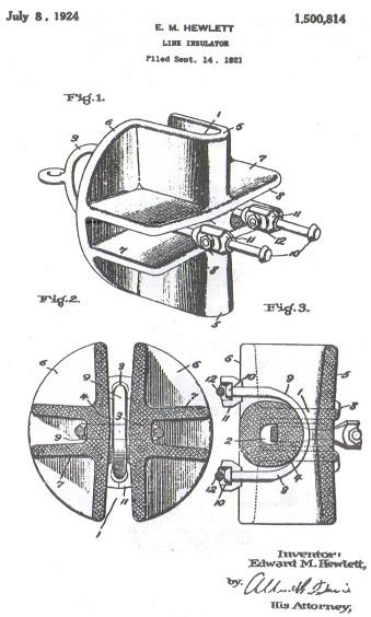
Hewlett was granted another patent on July 8, 1924 (application filed Sept.
14, 1921), for an unusual suspension disk with the same interlocking design.
This insulator had deep flanges formed in the body (see patent drawing) that the
patent claimed would help the insulator sustain higher mechanical and electrical
stresses. Similar U-bolt interconnecting hardware was used but with a slightly
different coupler. I'm fairly certain that I have seen one of these insulators
but don't recall who had it. I would be interested to hear from anyone
who has this insulator and would appreciate a good photograph of it.
This story would not be as complete without mention of a patent interference
suit. Louis Steinberger was granted a patent on November 17, 1908, upon his
application of January 20, 1908, which claimed an insulator quite similar to the
interlocking design claimed in the Hewlett patent application. Remember the
Patent Office had received the Hewlett application on April 20, 1907. Having
discovered the error, the Patent Office declared interference between the two
claims on November 2,1911. The Appeals Court ruled on October 9,1913, in favor of
Hewlett with an appeal being made to the Supreme Court. Steinberger wrote to
Buck in October 1905 detailing his idea; however, Buck had made sketches of his
invention in March or April 1904. I assume the Supreme Court ruled in favor of
Hewlett because his patent was granted on September 15, 1914.
For those of you
who do not know, Louis Steinberger was the owner of Electrose Mfg. Co. From
about 1900 to about 1929, he obtained dozens of mostly unimportant patents for
various uses of his composition insulators. The composition material used in the
Electrose insulators was similar to the early plastic known as Bakelite.
Electrose insulators were copies of many of the popular designs and many forms
of insulators were widely advertised. Literally every design and idea
Steinberger conceived was either granted a patent or advertised as being
available. Electrose insulators evidently obtained some continued success with
small customers; however, few of the unattractive specimens have found their way
into collections.
Electrose suspension insulator similar to
the Hewlett interconnecting design.
Illustration was taken from January 3, 1914,
issue of Electrical World.
| 
)
)
)
)
)
)
)
)
)
)
)
)
)
)